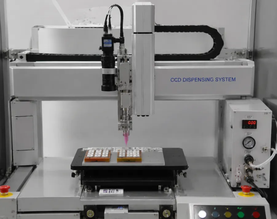
The Role of CCD in Dispensing
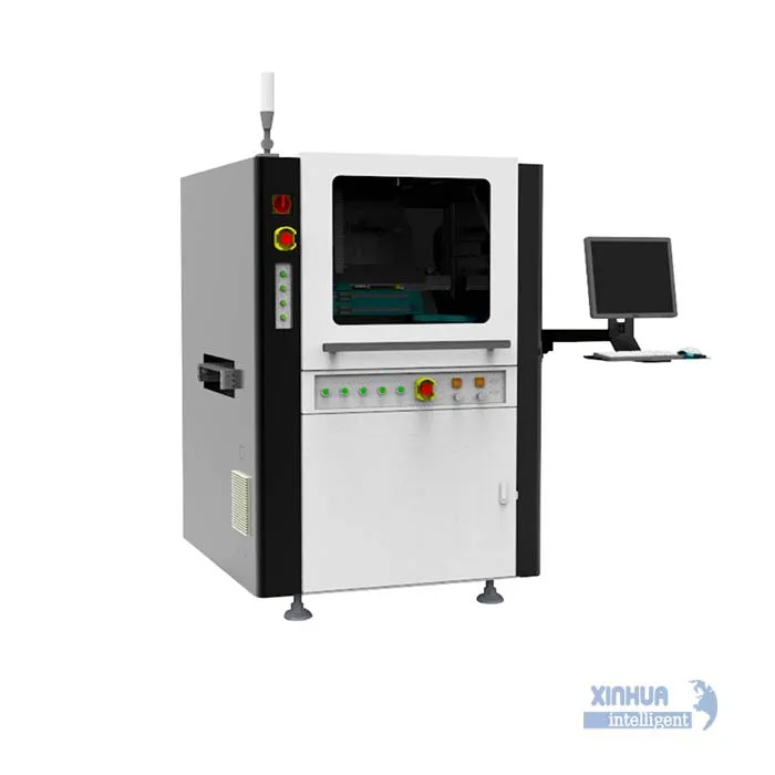
A CCD vision system uses high‑resolution digital cameras to capture real‑time images of the workpiece, typically illuminated by coaxial or ring lighting for optimal contrast. Dedicated software processes these images, identifying fiducial marks, edges, or unique surface features. The system then calculates the exact position, rotation, and scale of the part relative to the machine’s coordinate frame. This data is fed back to the motion controller, which adjusts the dispensing path before the first drop is placed. The entire cycle—from image capture to path correction—occurs in milliseconds, making it seamless within high‑volume production lines.
Primary Mechanisms for Accuracy Enhancement
1. Precise Fiducial Alignment
Even the best fixtures and conveyors introduce part‑to‑part variations—thermal expansion, pallet wear, or inconsistent loading. CCD systems locate standard reference marks (e.g., crosshairs, circles, or PCB corner pads) with sub‑pixel resolution, often down to 1‑2 microns. The dispenser then offsets its programmed path to match the actual part location, ensuring that adhesive lands exactly where intended, regardless of mechanical deviations.
2. Height and Z‑Axis Compensation
Many vision systems incorporate laser triangulation or structured light in addition to CCD cameras. They measure surface height at multiple points, creating a height map. This data allows the system to dynamically adjust the Z‑axis gap between nozzle and substrate, compensating for board warpage, component height variations, or uneven mounting. A constant standoff distance ensures consistent dot shape and volume, directly improving bond strength and preventing smearing.
3. Rotational Correction (Theta Compensation)
Parts may rotate slightly on the conveyor. CCD vision detects angular displacement by comparing the captured image to the design data. The motion platform then rotates the tool or the workpiece accordingly, aligning the dispense pattern to the part’s actual orientation. This is critical for rectangular or oblong patterns, where a few degrees of rotation can cause off‑center beads.
4. Real‑Time Process Monitoring and Adaptive Control
Advanced systems do not merely calibrate before dispensing; they also inspect after dispensing. Inline CCD cameras examine dot diameter, line continuity, and presence of adhesive, flagging off‑spec dispenses instantly. Some systems close the loop by adjusting pressure or valve open time on the fly, compensating for gradual changes in fluid viscosity or nozzle wear. This adaptive capability ensures that accuracy is maintained over thousands of cycles, not just at startup.
Tangible Benefits on the Production Floor
The impact is measurable. First, setup time plummets—operators no longer manually jog the machine to find reference points; the vision system does it automatically, reducing changeover from 15 minutes to under 30 seconds. Second, yield improves dramatically; typical defect rates drop from 2‑3% to below 0.2% in high‑mix assemblies. Third, tolerance to upstream variations increases; customers can use less expensive fixtures or allow board warp within reasonable limits, because the vision system compensates intelligently. Fourth, data traceability—every dispense cycle stores images and correction values, enabling root‑cause analysis and preventive maintenance.
Common Applications
CCV‑guided dispensing is indispensable in smartphone camera module assembly, where adhesive must not obscure the lens, and in medical micro‑fluidics, where channel misalignment renders the device unusable. In automotive radar and LiDAR production, the patterns are complex and require angular precision; vision ensures beam paths remain unobstructed. Even in LED display manufacturing, where thousands of chips are placed per panel, vision‑guided underfill dispense ensures uniform fillets without voids.
Integration and Best Practices
Successful implementation requires careful camera calibration—using a known grid pattern to map pixel coordinates to real‑world distances. Lighting must be stable and contrast‑enhancing; stray reflections can confuse the algorithm. Regular calibration checks (daily or weekly) preserve accuracy. Additionally, the vision software should be trained to handle varying backgrounds, as components often change color or texture.
CCD vision systems are not an optional add‑on for modern automatic dispensers; they are the cornerstone of micron‑level precision. By providing real‑time positional awareness, height sensing, and post‑dispense inspection, they bridge the gap between the digital program and physical reality. As electronic components shrink and adhesive patterns grow more intricate, the synergy between vision and dispensing will only deepen. Manufacturers who embrace this technology gain a definitive competitive edge—one measured not just in microns, but in reliability, efficiency, and customer trust. In the world of high‑precision assembly, seeing truly is believing—and dispensing.